|
|
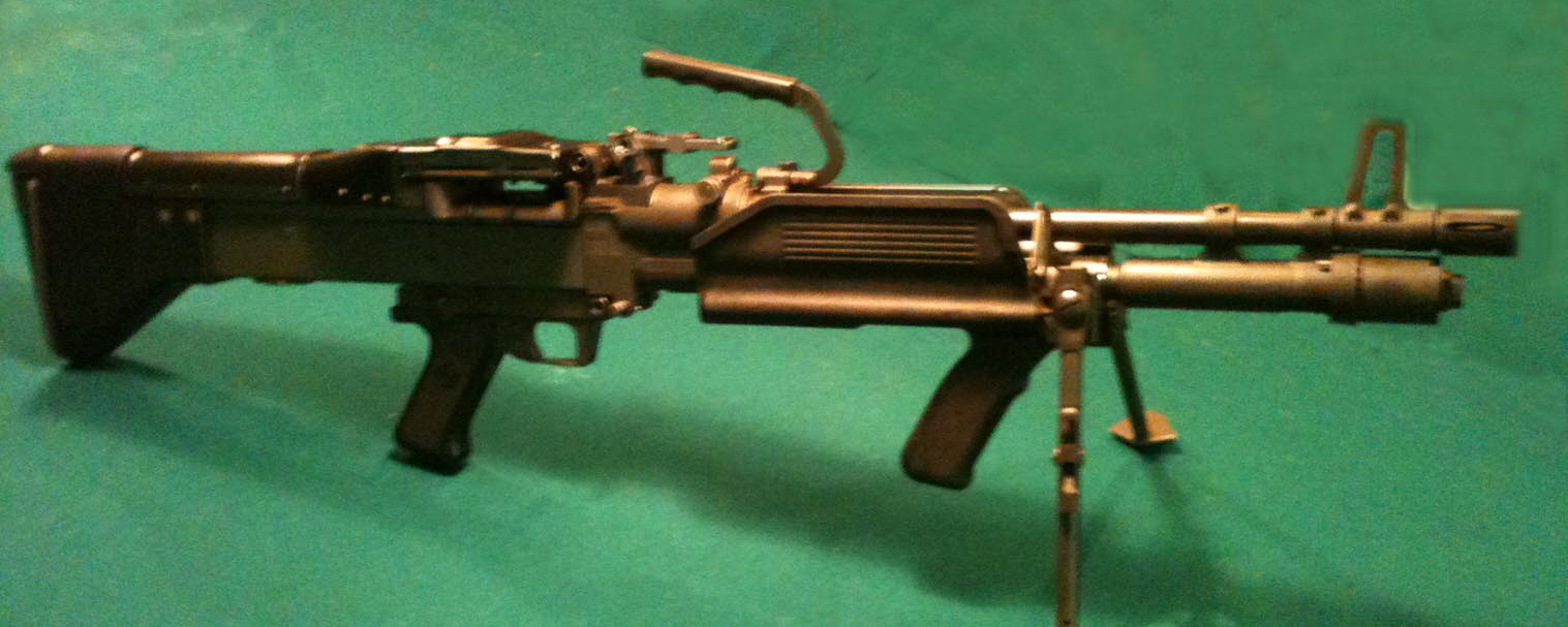
The following article(s) are republished with permission of the author, Thomas T. Hoel of Tactical Advantage. The articles were originally published as a 6-part series beginning in the November 2003 issue of Small Arms Review. All content © 2003-2017 by Thomas T. Hoel. The Civilian M60 Machinegun Owners Guide Receiver and Sub-Components: Damage Control Measures Now that we have explored the basic receiver assembly in detail, let us turn our attention to protecting and assuring its structural integrity and overall longevity. One of the greatest areas for potential problems with an M60 is centered on the receiver assembly, and its component parts. Because of the nature of the receiver being the NFA controlled item, and the general problem of receiver damages requiring expensive and difficult repairs, the Civilian owner should become quite familiar with common inspection procedures, and learn to avoid common potentially damaging operational actions. (The greatest source of damage to the trunnion, and its attached components, is from Operator abuse or carelessness.) The barrel trunnion is fortunate in that it does not have to contain any direct stresses of the firing cycle, but careless or abusive handling or neglect can still damage it. As first fielded in military service, the basic M60 receiver was assembled by riveted fasteners primarily, with press fitting and a small plug-weld being used to secure the gas tube (extremely early military production trunnions, extending into the T161 series, utilized a threaded and pinned fitting of the gas tube, but this was quickly amended in the production line when found to be not required, and replaced by a press-fit and plug-welded joint). After evidence of receiver separations in military use came to light a different, more secure, type of riveted fastener was tried as a cure, though with limited success. The approved fixative solution was the combination of the new enhanced-grip rivets and a series of welded seams to join the major subcomponents to the barrel trunnion, tying the individual subcomponents into a more solid, unitized, assembly. The welding operations are performed to join the barrel trunnion at its interface with the sheet-metal channel underside surface, the gas tube (Op-rod tube) at the trunnion socket, and the front side stubs of the milled bolt rails to their respective mating slots on the barrel trunnion. Once unitized by welding, the receiver assembly thus became an extremely strong and solid unit and this operation has virtually eliminated concerns over receiver separations. One of the very most important things for the civilian owner-operator to check for then is whether or not a specific commercially manufactured receiver has had this welding reinforcement done. A commercial receiver that is simply riveted and press fit together is very likely to offer a vastly reduced service life span and it is highly recommended that the proper welding reinforcement repairs be made before any further use of the gun. The specific welding operations are outlined in many of the Military Depot Level M60 maintenance manuals. (Dept. of the Army) TM 9-1005-224-23&P (revision May 1998 or later is preferred), is the best general repair reference manual commonly available and is highly recommended for reference, even if the gun owner does not anticipate undertaking any repair actions on his own. (The more commonly seen TM 9-1005-224-24 is the condensed version minus certain equipment lists, and is a very good substitute for general information) This TM, in which receiver inspection and remedial procedures are outlined, should be consulted to determine if a specific receiver has had the recommended reinforcements accomplished. For the conscientious owner one of the best pieces of peripheral maintenance equipment to own is the standard M60-series receiver gauge set (NSN 5220-00-921-5005); this standard gauge set is used to gauge receiver subcomponent alignment and serviceability by establishing angular displacement and stretch variances in all three planes. While it is primarily used to determine Even if the receiver in question has been weld reinforced it is positively necessary to periodically do a visual inspection of the welded joints for integrity, cracking, or other damage. As the standard gauge set is the only proper method to gauge receiver subcomponent alignment and serviceability by establishing angular displacement and stretch variances in all three planes as indicated above, periodic usage of the gauge is highly recommended, too. Since the welded receiver is now a much stronger unitized assembly, which is not free to "give" at the many points as an un-welded receiver will, any damaged weld joints may concentrate forces along small highly stressed areas if not corrected. This is most probable at the sheet-metal channel joint, and a damaged weld seam along the bottom of the trunnion there may cause long cracks to propagate well into the sheet-metal bottom of the receiver. Though easily repaired, a deep rend in the channel may eventually lead to more serious problems with the operating-rod and bolt. Aside from the above, the most commonly damaged area(s) of the receiver (trunnion) is the barrel socket, followed by the gas tube at the gas cylinder interface aperture. Both of these areas sustain damages from incorrect or abusive treatment of the barrel assembly where it mates into the receiver assembly here. Most importantly, these damages can be avoided in almost every case. The barrel assembly is extremely heavy for the amount of longitudinal support it receives within the trunnion, and all the weight is leveraged on the far fulcrum point of the bi-pod yoke, at the very end of the barrel itself. The entire mass of the barrel assembly is supported only by the rearmost 2½ inches of the barrel extension. (An additional ¼ inch of barrel assembly interface occurs at the circular lip of the gas cylinder nut when properly mated into the gas tube, but this in no way should be regarded as a true supporting interface.) Unless the tolerances of the mating interface is extremely tight and without measurable play, the continued movement of the barrel extension within the trunnion socket will eventually cause the socket tolerances to open up and expand the free play run-out. The barrel latch itself is really not designed or intended to hold the barrel extension tightly, simply to keep it from slipping out. The end result is that over time a trunnion socket that has become worn will not hold the barrel extension tight enough to hold a zero setting, the barrel will shift with every movement of the gun, sometimes to the point of causing jamming as the bolt lugs will not properly rotate to lock up in the locking cam ways of the barrel extension, stopping all use of the gun. It is virtually guaranteed that this wear will occur within the trunnion itself, as the barrel extension is far more hardened to wear. If the trunnion socket becomes excessively worn in this manner, or even driven out-of-round, expensive receiver repairs are the only option. Generally the only option available, aside from total replacement of the trunnion itself, is to align-bore the socket and sleeve it with a shimming sleeve of compatible alloy, suitably machined. Even if shrunk-fit or brazed into position, it may not be a permanent repair and may again loosen with heavy use. (WARNING! It has been noted on some civilian guns that sometimes an unfortunate owner faced with this problem has tried to solve it with an easier fix by applying a shimming sleeve to the barrel extension outer surface. This is patently ill advised as sleeving the barrel extension in this fashion only allows a bare 1¾ inches of clear outer surface to sleeve without interfering with the locking cam ways, and even if done carefully the bolt may still not be locking smoothly within its designed proper rotational alignment, causing undo strain and wear on the locking lugs of the bolt as well as increased wear on the barrel extension locking cam ways. This damage may not be immediately noticeable. Even then, trying to retain a shimming sleeve on the barrel extension surface may not be possible with complete safety, as any high temperature fixative methods may damage the critical heat treatment of the extension, upon which a large measure of it’s inherent strength depends.) All of this potential barrel assembly-to-receiver damage can be avoided almost completely, with two simple procedures that the civilian owner-operator can afford to take the time and care to put forth, whereas the military user likely cannot. Without arguing or belaboring the point of the design of the original model M60 bi-pod design and placement, it suffices to say that its location on the barrel assembly can lead to problems as concerns longevity of the weapon’s other operating assemblies. These specific problems began to be addressed way back with first military Product Improvement Program variant, the M60E1, and the civilian owner-operator now should be just as concerned as was the military then. And while the “recent” military adoption of the PIP’ed M60E3/E4 variants has given opportunity to address the original bi-pod situation to some degree, the following comments are valid to large degree even if a particular civilian M60 has been retrofit “upgraded” with the addition of the E3/E4 assemblies. The first problem is a simple one in that even though the gun was designed to be fired off the bi-pod in the prone position, in the designation role of “light machinegun”, to do so truly places a tremendous extra strain on the barrel trunnion socket, which over time will eventually lead to the problems outlined above. Compound this arrangement with the nearly universal tendency for operators to place heavy downward pressure on the gun when firing in an attempt to stabilize it and the induced moment-arm leverage strain can produce damaging results in a relatively short order of a few thousand rounds. Even if the E1/E3/E4 modifications have been performed to get the bi-pod support off the barrel and onto the gas tube, the use of the gun fired from the bi-pod position can lead to damages of the trunnion mating joint at the gas tube-trunnion interface, especially if the previously mentioned welding reinforcements have not been accomplished as may be the case with multitudes of commercially manufactured receivers. Gas tubes used on guns have been retrofit “upgraded” with the addition of the E3/E4 bi-pod assembly will experience additional strain along the tube itself, and longitudinal stress cracks are well known to develop along the tube body, particularly at the (relatively newly required) hole that has been drilled to accommodate the new-style fore-grip used on these configurations. The E3/E4 style modifications are at best a compromise “solution” to one set of problems, and bring to the gun a potential for a new set. Heavy users of a gun configured as an E3/E4 variant are wise to procure a spare gas tube, and be prepared to periodically weld repair their current one. The use of any bi-pod supported firing stance, with any M60 variant, may look appealing, but be forewarned that continued use of the weapon from that deployment can become a headache when the inevitable excess wear occurs. For the CIVILIAN owner-operator then, for maximum service lifespan and use of any M60 variant, the use of the self-contained bi-pod is NOT recommended!! The better arrangement, and the one that will lead to the longest life of the weapon, is to fire the M60 from one of the receiver supported mounts where the receiver is fully supported and the barrel places no unnecessary stresses into the trunnion barrel socket, or gas tube (or gas tube-trunnion interface). There are several military designed mounts for the M60 series, including tri-pod mounts, vehicle mounted pedestals of various descriptions, and even a dedicated M60 cradle mount (the M142 cradle assembly (PN 10900945) which incorporates a built-on 200-rd ammunition box hanger) for use with pedestal bases or vehicle sockets. Any of these are far better to fire the weapon from instead of the built-in bi-pod, as it is allows the receiver to be held in tighter retention to a heavy mount which can better handle the stresses of firing, also thereby increasing the ability to lay fire accurately. The most commonly encountered of these mounts is the US Standard M2 tri-pod, already in service for decades with the .30 cal. Browning series of machineguns, and useable with minimal adaptation to the M60 GPMG. The newer designation for the “current” manufacture M2 tri-pods is “Mount, Tri-pod, Machinegun, 7.62mm, M122 (PN 7790723/NSN 1005-00-710-5599)”, or more simply, the M122 tri-pod. For all practical purposes, the only real difference between the WWII (or earlier) vintage M2 tri-pod and the newer re-designated M122 is the date of manufacture. Both M2 and M122 require dedicated pintle adapters for use with the M60 (or specific M60 pintles), along with an M60-use specific T&E mechanism adapter bar; the tri-pods themselves are identical in all other ways. And even here, one can make better use of the available choices in civilian terms, than the military user. There are also two distinct designs and vintages of tri-pod pintle adapter/pintles available, although one version is clearly a better design for our discussion. Both will require the use of a dedicated M60 T&E mechanism adapter “H”-leg (PN 7792991/NSN 1005-00-772-0194) to tie the M60 receiver into the older Browning machinegun T&E mechanism. The earliest version of pintle adapter (PN 779284) was indeed a true adapter as its function was to adapt the M60 to use a standard Browning-style tri-pod pintle. This is usually referred to as the “pintle adapter platform”, or early-issue “pintle-platform assembly”. It has two distinct advantages over the late-issue M60-dedicated pintle, commonly known as the “Gooseneck pintle”, in that by using the pintle-platform adapter the receiver is tightly held along the majority of the underside of the weapon, retained by the pintle mount pin and locking into an additi The (current) late-issue M60-dedicated pintle (PN 11010408/NSN 1005-00-945-9756), commonly known as the “Gooseneck pintle” was an attempt to render the M60, when used in the “heavy” machinegun role, a more manageable package by reduction of weight and simplification of design. It’s main feature is that it does not require use of the old Browning-style pintle in that it is a single unit which combines the tri-pod pintle function with a single-point receiver mount pin latch. Unfortunately, though weight was shaved, utility and stability were sacrificed. The only real advantage over the early-issue platform style was that due to its single-point mounting to the receiver, the gun could be traversed and elevated by hand (free swung) on an advancing target more quickly and with less physical force, though even when tied to the T&E mechanism stability when firing was considerably reduced as the gun was simply not as rigidly mounted as before. It was trade off that found many supporters, but for the general rule of keeping stresses off the gun and instead transmitting them into the mounting, it is not nearly as good a choice. It also caused more strain to be put into the T&E mechanism and adapter leg, and it is commonly noted that the lugs of the T&E adapter mounting plate under the receiver channel will show signs of wear and deformation more rapidly when used with the late-style pintle; loosening of the two attachment rivets is fairly common. These late-style “Gooseneck pintles” are currently also quite available, though asking prices vary widely, and they are certainly not rare or hard to find. For the most secure receiver mounting, and greatest stability when actually firing, the gun should be mounted securely either tied into a pintle mounting or mounted into a dedicated vehicle cradle assembly. On the M2/M122 tri-pod, the early-issue “pintle-platform assembly” is clearly the superior equipment, though either version of pintle mount provides superior receiver support, and consequent reduction in barrel assembly induced stresses, than firing off the self contained bi-pod. However, even when mounted onto a tri-pod, pedestal yoke, or vehicle cradle mount there is still more that can be done to reduce barrel assembly-induced strain on the trunnion socket and gas tube. The M60E1 variant pointed the way, and was confirmed in the later E3/E4 variants. The high levels of induced strain are a combination of the small surface contact area of the barrel extension in the trunnion socket, combined with the very heavy weight of the barrel assembly itself. While there is nothing to be done about the barrel mounting and retention design situation, one can reduce the operational weight of the entire barrel assembly by following the lead of the M60E1 program. The current E3/E4 variants are the result of two different objectives. The first was to reduce overall weight of the individual machinegun to ease the loading burden of the weapon on the soldier in the currently in vogue rapid-reactive deployment scenarios, the second objective was to provide for operational improvement in several previously identified areas of concern. This resulted in the combined effects of relieving the barrel assembly of its bi-pod unit, greatly reducing the actual mass of the tube by reducing the diameter and length, and a thorough redesign of the gas system. As such, either of the E3/E4 variant barrel assemblies is efficient at reducing stresses on the trunnion, but this comes at an operational penalty that seems particularly relevant to many civilian users. The reduced mass of these redesigned barrel units greatly reduces their ability to fire in a sustained fashion, something all too many civilian users seem to disregard!! If proper fire discipline can be maintained as intended with the E3/E4 barrel groups, they are the ideal choice so far as limiting receiver wear is concerned due to their greatly reduced weight, though they are considerably more expensive than the standard M60 barrel group even if purchased used. For most circumstances of civilian recreational shooting, a better option can be created from a slight modification of an original standard “heavy” M60 barrel group to optimize it for use with a fixed receiver mounting, such as a tri-pod or cradle mounting. As it is, the original “heavy” profile barrel is probably the best choice for the civilian recreational shooter as it is designed to handle a far greater volume of sustained fire and can tolerate considerably more abuse. A simple modification to remove the complete bi-pod group and original flash hider will result in a dedicated barrel assembly that is in the best possible configuration for use with the rigid receiver mounting options discussed above. To complete the ‘conversion’, the use of the newer M60E3 “short” birdcage style flash hider will render a highly efficient, and cosmetically pleasing package. This is an efficient and cost effective method to duplicate a majority of the advantages found in the M60E3/E4 barrel groups, while gaining an advantage over them in terms of recreational shooting utility due to the retention of the full barrel profile. Handling in this configuration also improves markedly, as the reduction in weight at the end of the barrel is significant, greatly narrowing the advantage enjoyed by the newer barrel versions. Part 3 will begin a detailed discussion of the peripheral assemblies that complete the weapon, with an added emphasis in the discussion provided on general service recommendations particularly appropriate for the civilian recreational shooter. Part 3 - Barrel Group Basics |
 receiver serviceability limits, it is also the required and specified tool to use to provide correct alignment of the receiver subcomponents when initially placing receiver reinforcing weldments by properly positioning and holding the various subcomponents that attach to the primary receiver component, the trunnion, during primary tack-welding operations. Attempting to weld the subcomponents to the trunnion without this critical alignment holding tool will invariably result in the receiver actually being assembled and held together in an un-aligned, or even twisted, configuration. If this has happened critical wear surfaces between the receiver rails, op-rod, bolt roller, or other stressed parts will almost surely develop leading to excessive or detrimental wear patterns being established that will severely limit the useful lifespan of these components as they are forced to wear together. (A gun that exhibits a difficult or hard to retract cocking motion should immediately be checked for proper receiver alignment with the standard gauge set, followed by careful examination of the reciprocating parts involved, inspecting for unusual wear patterns or locations.)
 onal mounting pin on the gas tube.
  It is this two-point retention that gives the pintle-platform adapter its’ exceptional rigidity and stability. Also of great value, is that since it is designed to interface with a standard M2 pintle, it may be used anywhere the older Browning pintle was intended to be mounted. This is highly useful as it allows the M60 to be mounted into any of the traditional GI pedestal mounts formally used with the Browning 1919/AN-M2 series of machineguns. These are common as the ubiquitous M24 or M25 “Jeep” or vehicle pedestals, as they are equipped with a “yoke” type of mounting that takes the place of the separate M2 tri-pod pintle itself. The M60 pintle-platform adapter will simply slide into the yoke of the M24/M25 pedestal frame like it would in the tri-pod pintle. With this set-up a superbly stable and very useful “stand-up” mount may be put together using off-the-shelf military standard components! Mounted thusly, and with the pedestal bolted to a suitably heavy legwork frame base, or vehicle, the M60 remains absolutely rock solid when firing totally giving it a whole new personality. (Many people who have shot an M60 from the bi-pod prone and not liked it, will utterly do an about face when allowed to shoot it from a solid, stable mounting.) Currently, the early issue pintle-platform adapter style of mounting is cheap and plentiful and is wholly recommend as the one piece of equipment to have when mounting the M60 into a tri-pod setting, plus it is the only pintle form that will allow use of GI pedestal mounts using off-the-shelf military standard components.
|
[Home] [Price Guides] [Beltfed] [M60 Part 2] |
|
Copyright © 2006-2025 PJW - All rights reserved [Sitemap] Comments to topgun@machinegunpriceguide.com |